【光谱实验室:陈中博士 撰文】
【仪器设备:傅里叶变换显微红外光谱仪】
【地点:4号楼220室 光谱实验室】
相比于透射KBr压片测试,衰减全反射(ATR , Attenuated Total Reflectance)技术在测试过程中不需要对样品进行任何处理,也不会造成对样品的损坏,已经成为傅里叶变换红外光谱(FTIR)测试的重要手段。理化平台光谱实验室的Nicolet iS50 高端研究型傅立叶红外光谱仪集成目前最先进的电子和数字技术, 内置中红外ATR,无需制样,平均2分钟之内可以完成固体、液体、薄膜样品的测试,同时也减少用户每次使用ATR附件的安装和拆卸过程。下面具体介绍ATR 附件的工作原理。

图1. 单色光的反射,折射和全反射
当一束单色光从一种介质(n1)射向另一介质时(n2),将在界面发生反射和折射现象,如图(1)所示,由反射定律,反射角β等于入射角α。由折射定律:sinα/sinγ=n2/n1 (n1为入射介质的折射率,n2为折射介质的折射率)。当光疏介质进入光密介质,n2>n1,如图1-a,其中一部分光会发生反射,反射角β等于入射角α,另一部分光发生折射,折射角γ小于入射角α。
反之,如果单色光从光密介质(晶体)射向光疏介质(空气或者材料)时,如图1-b, 同样也会发生反射和折射,此时晶体的折射率(n1)大于空气的折射率(n2),所以折射角γ1大于入射角α1。随着入射角的增大,折射角也随之增大,当入射角增到某一角度α2时,折射角γ2等于90°,此时,折射光沿着晶体界面传播,如图1-c所示,此时的入射角称为临界入射角α2,sinα2=n2/n1 (n1为晶体的折射率,n2为折射介质的折射率)。如果继续增大入射角,则折射光消失,所有的光都以反射光的形式在晶体内部存在,发生全反射效应。
大多数有机物的折射率都低于1.5,根据折射定律,要获得衰减全反射光谱需要折射率大于1.5的红外ATR晶体,常用的 ATR 晶体材料有:金刚石、ZnSe(硒化锌)、锗( Ge)、氯化银( AgCl)、溴化银( AgBr)、硅( Si),尤以金刚石应用最多。
ZnSe是一种价格相对低廉的ATR晶体材料,常用于分析液体以及凝胶类材料。其缺点是在pH在5-9时并不稳定,而且在清洁时较易产生划痕。相较于ZnSe,Ge所适用的pH范围较为宽泛,且可用于分析弱酸和弱碱。在所有的晶体材料中,Ge的折射率最高,因此它的穿透深度为1µm,适合测量表面信号(在1000cm-1处约为1.9µm,ZnSe晶体则约为6µm),且吸收光谱强度较弱,适合于测定强吸收和折射率高的样品,如填充炭黑的聚合物。Ge晶体测量的光谱区间较窄,低频只能测到800cm-1左右。而金刚石材料由于其具有较好的坚固性和耐磨性,被称为最佳的ATR晶体。尽管制造成本较高,但材质坚硬可极大延长仪器的使用寿命,这一点是其它材料不可比拟的。金刚石晶体在1800-2700cm-1范围内有吸收,在测定腈类(特征吸收在2200cm-1附近)等物质时应避免使用。该附件相较于锗晶体ATR附件更耐压,样品与晶体接触更紧密,入射深度更深,更易得到较好的红外光谱图。Nicolet iS50光谱仪正是采用金刚石作为ATR晶体材料。
附表1 常用晶体材料的性质
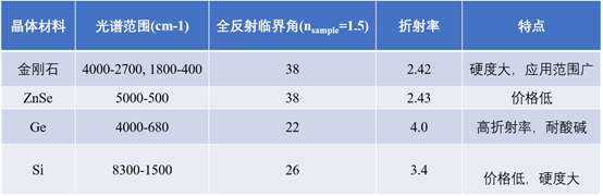
从表1可以看出,晶体的折射率越小,全反射临界角越大。实际上,不仅反射角和折射角与入射角有关,而且反射光和折射光的强度也有入射角有关。当入射角增大时,反射光的越来越强,折射光变弱。达入射角>=临界角时,折射角>=90°,折射光的光强为0,反射光强等于入射光强,发生全反射。ATR附件就是基于这种全反射原理而设计的。
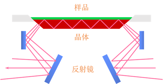
图2. 水平ATR附件光路图
图2是水平ATR附件的光路示意图,待测样品在晶体上方,红外光束在晶体内发生多次衰减全反射后到达检测器。如上图所示,发生全反射时,红外光束并没有穿越晶体表面进入样品,那么红外光是怎样与待测样品发生作用?实际上,红外光在晶体内表面发生全反射时,会在晶体外表面附近产生驻波,称为隐失波,如图3所示,样品与晶体外表面接触时,在每个反射点隐失波都穿入样品。从隐失波衰减的能量可以得到吸收信息。隐失波振幅随离开晶体界面距离的增大按指数规律衰减。当隐失波振幅衰减到原来振幅的1/e时的距离为穿透深度。穿透深度D由下式计算,取决于入射光的波长λ,晶体的折射率n1,样品的折射率ns,和光束在晶体界面的入射角α。
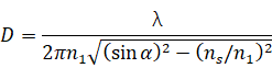
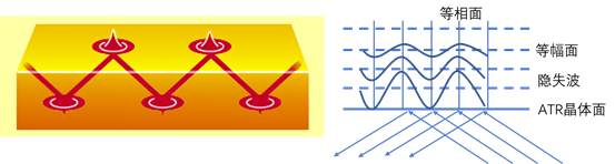
图3. 隐失波及其等幅面和等相面
根据公式,影响穿透深度D正比于样品折射率ns及入射光波长λ,反比于入射角α及晶体材料折射率n1。有机物的折射率一般小于1.5,取ns为1.25,采用金刚石作为晶体材料,入射角为45°,计算出的穿透深度为0.1λ。在4000-400cm-1区间的D值为0.25 - 2.5mm,穿透深度在高频和低频相差一个数量级,需要校正后才能和普通的透射法进行比较,本仪器在调用测试参数时已包含了ATR校正参数,无需后续的手动校正。
在计算穿透深度时,样品和晶体是一种理想接触,实际上,只有空气、液体与晶体的接触属于这一类,而粉末、薄膜、块状固体样品的接触并不能达到理想接触,穿透深度会小于计算值。然而,在使用单次反射ATR附件测试时,如图4,样品与ATR晶体的接触面很小,附件上方安装了压力杆,测试固体样品时,在施压的作用下可以保证样品和晶体的紧密接触,压力杆上有力矩旋钮,不管样品的大小和形状如何,都能保证施加压力相同,也能保证ATR晶体不会压坏。虽然测试固体过程中只有一次全反射,也能得到高质量的光谱。
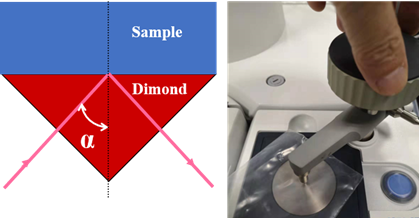
图4. 单次ATR附件及光路
以上主要总结了傅里叶变换显微红外光谱仪之ATR附件的基本原理,后续我们还将会推出以测试实际样品的数据分析来阐述其应用方面的专题,欢迎大家来理化平台光谱实验室讨论和使用傅里叶变换显微红外光谱仪。
Principle of ATR accessory in Fourier transform micro - infrared spectrometer
Compared with KBr infrared tablet transmission method, ATR (Attenuated Total Reflection) technology needn’t any treatments and wouldn’t cause damage to the sample, has become a powerful tool in Fourier transform infrared spectroscopy (FTIR). The research-based FTIR Nicolet iS50 at ISCPS lab incorporates the latest electronic and digital technology and equips with a built-in mid-infrared ATR accessory, which is used to directly analyze solid, liquid or film samples within two minutes, and also reduces the installation process of ATR accessory. The working principle of ATR accessory is introduced in detail below.
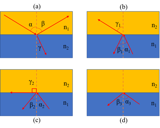
Figure 1. Reflection, refraction and total reflection of light
When incident light shoots from one material (n1) into another material (n2), reflection and refraction will occur at the interface, as shown in Figure1. Based on the law of reflection, the reflection angle is equal to the incident angle. According to the law of refraction: sinα/sinγ =n2/n1 (n1 is the refractive index of incidence material 1, and n2 is the refractive index of refraction material 2). When n2>n1, as shown in Figure 1a, part of the light will be reflected that reflection angle β is equal to incident angle α, and the other will be refracted that refracted angle γ is less than incident angle α.
On the other hand, if the monochromatic light shoots from the optically-denser medium (crystal) to the optically-thinner medium (air or material), as shown in Figure1b, reflection and refraction will also occur. In this case, the refractive index of the crystal (n1) is larger than the refractive index of the air or sample (n2), so the refracted angle (γ1) is larger than the incident angle (α1). As the incident angle increases, the refracted angle also increases. When the incident angle increases to a special angle (α2), the refracted angle (γ2) is equal to 90°. At this point, the refracted light emits along the crystal interface, as shown in Figure1c. If the incident Angle continues to increase, the refracted light disappears, and all the light reflected back to the inside of crystal, resulting in a total reflection effect.
Most refractive index of organics are lower than 1.5, based on the total reflection condition (n1 > n2), attenuated total reflection happens when the refractive index of ATR crystal larger than 1.5. Nowadays, commonly-used ATR crystal materials include diamond, ZnSe (zinc selenide), germanium (Ge), silver chloride (AgCl), silver bromide (AgBr), silicon (Si), and diamond.
ZnSe is a relatively inexpensive ATR crystalline material that is commonly used in the analysis of liquids and gel-like materials. But it is not stable in pH5-9, and easily be scratched when cleaning its surface. Compared to ZnSe, Ge material can be applying in a wide range of pH include weak acids and bases. Ge has the highest refractive index of all crystalline materials, so its penetration depth is about 1 µm that suitable for surface information collecting (about 1.9 µm at 1000cm-1, and about 6 µm for ZnSe crystals), and the strength of absorption spectral is weak, all of which make it better for the measurement of high refractive index and strong absorption and samples, such as polymers filled with carbon black. However, the spectral range of Ge crystals is narrow that low frequencies measuring only around 800cm-1. Diamond crystal has good rigidity and wear-resistance which become the best ATR crystal. Despite it is very expensive, the hardness of the material can greatly extend the service life of the instrument that is incomparable to other materials. The spectral range of diamond crystals from 1800 cm-1 to 2700 cm-1 should be avoided because of its absorbance in that range, so it is not suitable for measurement of nitrile (characteristic absorption near 2200cm-1). Even though, diamond crystal still become the most ideal ATR crystal materials to collect infrared spectrum since its higher pressure-resistant that make the sample contact with the crystal tightly, and the incident depth is deeper. The Nicolet iS50 spectrometer also uses diamond as ATR crystal material.
Table 1 Properties of crystalline materials
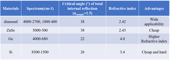
As shown in table 1, the smaller of the refractive index in crystal, the larger of the critical angle of total reflection. In fact, not only does the reflection angle and the refraction angle depend on the incident angle, but also the intensity of the reflected light and refracted light depend on the incident angle. As the incident angle increases, the reflected light becomes stronger and the refracted light becomes weaker. When the incident angle >= critical angle, then the refraction angle >=90°, leading to the intensity of the refracted light is 0, and the intensity of reflected light is equal to the intensity of incident light, that is, total reflection happens. ATR accessory is based on this principle of total reflection.
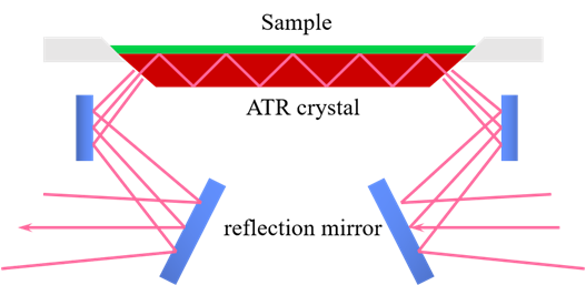
Figure 2. Optical path of horizontal ATR accessory
Figure 2 shows the optical path of the horizontal ATR accessory. The sample is above the crystal, and the infrared beam reaches the detector after several times of total reflection attenuation in the crystal. As shown in the Figure 2, when total reflection occurs, the infrared beam does not pass through the crystal surface to enter the sample, how does the infrared light interact with the sample to be tested? In fact, when the total reflection of infrared light occurs on the inner surface of the crystal, a kind of standing wave, called evanescent wave, will be generated near the outer surface of the crystal. As shown in Figure 3, when the sample is in contact with the outer surface of the crystal, evanescent wave will penetrate the sample at each reflection point, and the absorption information can be obtained from the energy attenuation of the evanescent wave. The amplitude of the evanescent wave decays exponentially as the distance away from the crystal interface. When the amplitude of the evanescent wave decays to 1/e of the original amplitude, the distance called the penetration depth (D). The penetration depth D is calculated by the following formula, depending on the wavelength of the incident light λ, the refractive index n1 of the crystal, the refractive index ns of the sample, and the incident angle α.
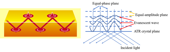
Figure 3. Equal-amplitude and Equal-phase plane of Evanescent waves
According to the formula, the penetration depth D is proportional to the incident wavelength (λ) and refractive index of sample (ns), inversely proportional to the incident angle (α) and refractive index of the crystalline material (n1). Generally , the refractive index of organic matter is less than 1.5. We select ns as 1.25, diamond as the crystalline material, and the incident angle as 45°, from which the calculated penetration depth D is 0.1λ. So, the D value in the range of 4000-400cm-1 is 0.25-2.5 mm, which reaches one order of magnitude difference between high frequency and low frequency. The result needs to be corrected when compared with the traditional transmission method. The ATR accessory in our lab includes ATR correction function without any subsequent manual correction.
The calculation of penetration depth D above bases on the hypothesis that the sample and the crystal are an ideal contact. In fact, the ideal contact only happens between air (or liquid) and the crystal, while the powder, film and block solid samples cannot reach the ideal contact which result in the penetration depth D less than the calculated value. However, in the use of a single reflection ATR accessory, as shown in Figure 4, the contact area of samples with the ATR crystal is small, and the installed pressure rod above the ATR crystal can ensure the tighten-contact between sample and crystal. The torque-controlled pressure rod also can guarantee the same pressure on sample, ensuring the ATR crystal wouldn’t be crushed. Although there is only one total reflection happens during the solid sample test, high quality spectrum could be obtained.
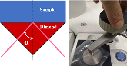
Figure 4. Single Reflection ATR accessory and its optical path
Herein, we summarized the basic principle of the ATR accessory of Fourier transform microscopic infrared spectrometer. In the future, we will continue to introduce its applications by analyzing the data of actual samples. Welcome to the Spectroscopy Laboratory of ISCPS to discuss and use Fourier transform microscopic infrared spectrometer.
参考资料:
1. 傅里叶变换红外光谱分析 翁诗甫,徐怡庄 编著 2017 化学工业出版社